Introduction
On this page you will find a number of MyHDL descriptions of flip-flops and latches.
Typically, you wouldn't describe flip-flops and latches as individual modules. Rather, they can be inferred from higher-level RTL description by a synthesis tool. However, as these circuits are small and widely known, they are well suited to explain basic MyHDL usage and to compare MyHDL with other solutions.
D flip-flop
Specification
The basic D flip-flop is a sequential device that transfers the value of the
d input to the q output on every rising edge of the clock clk.
Description
Here is the description of a D flip-flop in MyHDL:
from myhdl import *

@block
def dff(q, d, clk):

    @always(clk.posedge)
    def logic():
        q.next = d

    return logic
Simulation
Let's add a small test bench to simulate the design:
from random import randrange

@block
def test_dff():

    q, d, clk = [Signal(bool(0)) for i in range(3)]

    dff_inst = dff(q, d, clk)

    @always(delay(10))
    def clkgen():
        clk.next = not clk

    @always(clk.negedge)
    def stimulus():
        d.next = randrange(2)

    return dff_inst, clkgen, stimulus


def simulate(timesteps):
    simInst = test_dff()
    simInst.config_sim(trace=True, tracebackup=False)
    simInst.run_sim(timesteps, quiet=0)

simulate(2000)
Function test_dff creates an instance of the D flip-flop, and adds a clock
generator and a random stimulus generator around it.
Function simulate simulates the test bench. Note how the MyHDL function
traceSignals is used to create the test bench instance (instead of calling
test_dff directly). As a result, a signal trace file will be created during
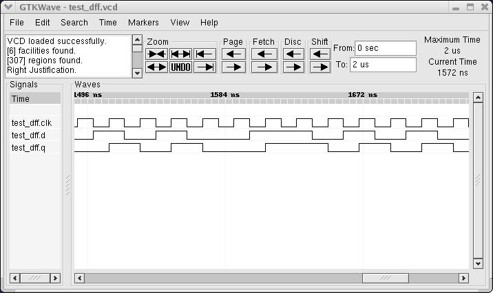
simulation. This file can be inspecting in a waveform viewer. As a verification
method, inspecting waveforms has its drawbacks, but it can be very effective to
debug small designs.
Here's a screen shot of the simulation waveforms:
Automatic conversion to Verilog or VHDL
With MyHDL's convert function, a D flip-flop instance can be converted to
Verilog or VHDL code:
def convert():
    q, d, clk = [Signal(bool(0)) for i in range(3)]
    convInst = dff(q, d, clk)  #, 'Verilog')
    convInst.convert(hdl='Verilog')
    convInst.convert(hdl='VHDL')

convert()
This is the resulting Verilog code:
module dff (
    q,
    d,
    clk
);

output q;
reg q;
input d;
input clk;

always @(posedge clk) begin: DFF_LOGIC
    q <= d;
end

endmodule
D flip-flop with asynchronous reset
Specification
One of the most useful sequential building blocks is a D flip-flop with an additional asynchronous reset pin. When the reset is not active, it operates as a basic D flip-flop as in the previous section. When the reset pin is active, the output is held to zero. Typically, the reset pin is active low.
Description
Here is the description:
from myhdl import *

@block
def dffa(q, d, clk, rst):

    @always_seq(clk.posedge, reset=rst)
    def logic():
        if rst == 0:    # nRst ?  or use active high ?
            q.next = 0
        else:
            q.next = d

    return logic
Simulation
Here is a test bench for the design:
from random import randrange

@block
def test_dffa():

    q, d, clk = [Signal(bool(0)) for i in range(3)]
    rst = ResetSignal(val=1, active=0, isasync=True)

    dffa_inst01 = dffa(q, d, clk, rst)

    @always(delay(10))
    def clkgen():
        clk.next = not clk

    @always(clk.negedge)
    def stimulus():
        d.next = randrange(2)

    @instance
    def rstgen():
        yield delay(5)
        rst.next = 1
        while True:
            yield delay(randrange(500, 1000))
            rst.next = 0
            yield delay(randrange(80, 140))
            rst.next = 1

    return dffa_inst, clkgen, stimulus, rstgen


def simulate(timesteps):
    simInst = test_dffa()
    simInst.config_sim(trace=True, tracebackup=False)
    simInst.run_sim(timesteps, quiet=0)

simulate(2000)
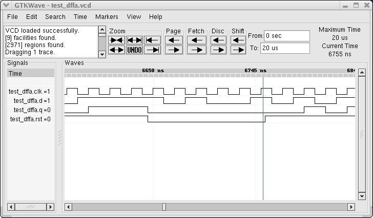
Compared to the test bench for the basic D flip-flop, there is an additional reset generator, that generates reset pulses at random moments and with a random duration.
Here is a screen shot of the waveforms:
Automatic conversion to Verilog or VHDL
The design can be converted to Verilog and VHDL:
def convert():
    q, d, clk = [Signal(bool(0)) for i in range(3)]
    rst = ResetSignal(val=1, active=0, isasync=True)
    convInst = dffa(q, d, clk, rst)
    convInst.convert(hdl='Verilog')
    convInst.convert(hdl='VHDL')

convert()
The VHDL result looks like this:
entity dffa is
    port (
        q: out std_logic;
        d: in std_logic;
        clk: in std_logic;
        rst: in std_logic
    );
end entity dffa;

architecture MyHDL of dffa is
begin
DFFA_LOGIC: process (clk, rst) is
begin
    if (rst = '0') then
        q <= '0';
    elsif rising_edge(clk) then
        if (rst = '0') then
            q <= '0';
        else
            q <= d;
        end if;
    end if;
end process DFFA_LOGIC;

end architecture MyHDL;
Latch
Specification
A basic latch is a sequential device with an input, and output and a control gate pin. When the gate is open, the output follows the input combinatorially. When it is closed, the output keeps its value.
Description
The following code describes a latch:
from myhdl import *

@block
def latch(q, d, g):

    @always_comb
    def logic():
        if g == 1:
            q.next = d

    return logic
Note the usage of the always_comb decorator. This is somewhat of a misnomer.
(The name comes from a similar construct in SystemVerilog). It doesn't mean the
generator describes a circuit that is necessarily combinatorial, but merely
that it triggers whenever one of the input signals changes.
Simulation
Here is a test bench to simulate the latch:
from random import randrange

@block
def test_latch():

    q, d, g = [Signal(bool(0)) for i in range(3)]

    latch_inst = latch(q, d, g)

    @always(delay(7))
    def dgen():
        d.next = randrange(2)

    @always(delay(41))
    def ggen():
        g.next = randrange(2)


    return latch_inst, dgen, ggen

def simulate(timesteps):
    simInst = test_latch()
    simInst.config_sim(trace=True)
    simInst.run_sim(timesteps, quiet=0)

simulate(2000)
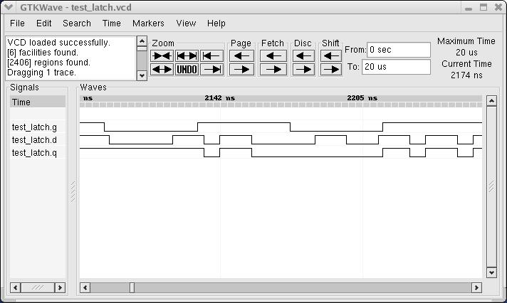
In addition to the latch instance, the test bench creates a random data generator for the input and for the controlling gate.
Here is a screen shot of the simulation waveforms:
Automatic conversion to Verilog or VHDL
We can convert the design as follows:
def convert():
    q, d, g = [Signal(bool(0)) for i in range(3)]
    convInst = latch(q, d, g)
    convInst.convert(hdl='Verilog')
    convInst.convert(hdl='VHDL')

convert()
Here is the verilog result:
module latch (
    q,
    d,
    g
);

output q;
reg q;
input d;
input g;

always @(g, d) begin: LATCH_LOGIC
    if ((g == 1)) begin
        q = d;
    end
end

endmodule
Note that when the convert function converts the always_comb decorator,
it infers which signals are used as inputs to the always block